A Floppy Disk Drive Box Introduction
As time goes by my main S-100 system grew from a pair of full height Shugart
8" floppy disks to a system of many drives -- both hard and soft (CF Cards).
Recently it became apparent to me that I needed more desk surface space and
in general needed to tidy things up. At the back there was a "rats
maze" of power connectors with no indication of what was connected to what.
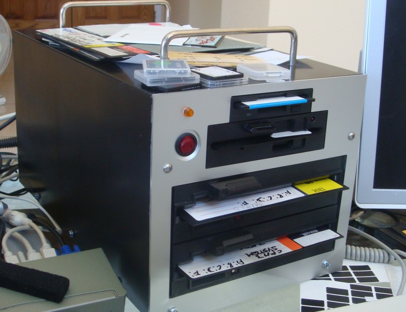
I decided to build a custom box to house two half height Tandon DSDD
(TM848-2) 8" drives, a 360K 5" drive and a 1.2M floppy drive. All
these are controlled by the Z80 based WD2793 FDC S-100 Board the (ZFDC
Board). At the back of the box I left room for up to 10 power
connector sockets! Here is a picture and brief build description of
the box:-
I do not have or have access to a proper machine shop for metal working.
Realizing my skills are limited in that section I had the metal work
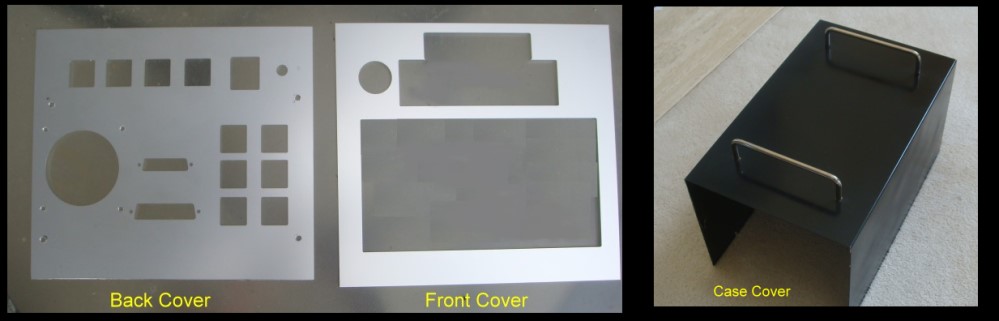
fabricated by two outside groups. The front and back panels were done by
Front Panel Express. They do great work and have a one week turn around.
Here are the files
I sent them. Here is a picture of the returned panels:-
The cover itself I had made by an outfit called
ShortRunPro. Unfortunately their
web site no longer has the file/dimensions I sent. But the web site allows
you to fabricate on line what you want. Start with "Build Bracket", then
select "U Bracket".... Unfortunately they take a few weeks to deliver.
The whole unit is built from a 1" thick slab of Plexiglass. Holes are cut in
it for drive mounts and panel supports using sheet metal screws.
The Back Panel
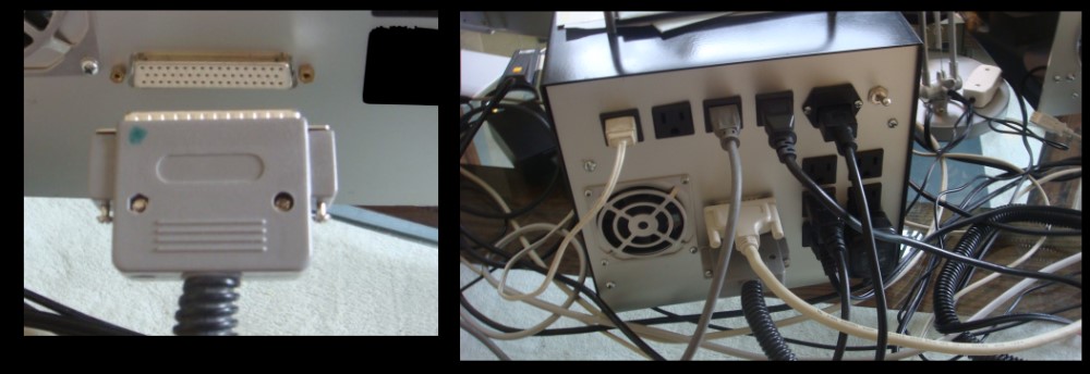
For the back panel I wanted to have as many 120V sockets as I could fit to
cleanup the cable connections at the back of my system. I have
one master switch to turn everything off, a small 12 volt fan to make sure
the drives/power supply (see below) does not get hot and two
connectors for the floppy disk drives (see below). I must
caution you we are dealing with potentially lethal 120 Volts, so be careful.
Also with this many outlets the total ampage must be carefully figured in so
as not to blow fuses. Most of the devices I have connected to these outlets
utilize only a few 100mA. But do your own math. Also be sure you
have the correct live, neutral, and ground orientations for each socket.
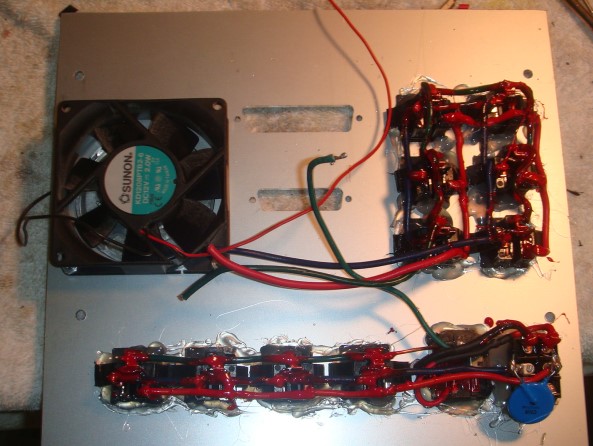
Check each (or use a socket tester). Here is a picture of the power
outlets attached to the back panel:-
Note how I have covered all solder joints with electrical insulating paste.
This is as a safety net in case any 5V/12V wire in the box accidently
touched the connections -- potentially causing serious damage to the whole
system. The AC power outlets (10) are the snap-in type (Jameco
#2114095). The single power inlet has its own fuse box -- also snap-in,
(Jameco #117445). I added one Varistor (blue) to deal with power line
spikes.
Next we need to add connectors to connect the Floppy disk drives to the ZFDC
controller board. The latter take a 34 pin and 50 Ribbon cable.
You can use this -- and you should test the system first with such a pair of
cables -- but I like to have the convenience of a multi-stranded cable.
I made my own custom cable utilizing only the 8" and 3.5" floppy signal
lines that are actually used. (Most simply go to ground).
However over extended lengths the critical data and clock signals were sent
via grounded coax cables. This on a scope gave better signals than a
ribbon cable. The connectors were carefully assembled by checking and
re-checking that each pin from the ZFDC ribbon cable connector ended up
correctly at the appropriate drive pin. This takes a lot of time
an care. Each line should be shielded with heat shrink tubing within the
sockets.
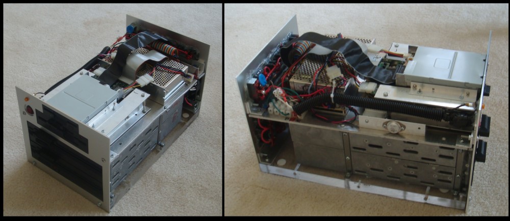
Here are some pictures of the finished drive box:-
You will note that the 5" and 3.5" drives are built on their own aluminum
platform. This is supported directly over the two 8" drives by four column
supports.
The custom end plates are attached with right hand brackets. The whole unit
is in fact quite heavy, but very strong.
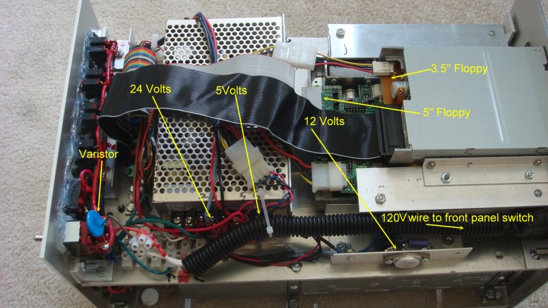
The Power Supply
The 8" drives require 120 Volts (for the drive motor), 24 and 5 Volts.
The latter two are supplied by a single switching regulator I obtained from
a group called PowerFactor.
I got their 24+5 Volt unit (D-128B). The 5" and 3.5" drives require 12 volts for their drive motor. This I
constructed myself using a TO-3 (a 7812), regulator using the 24 volt line
as an input.
Here is a final layout:-
Other pages describing my S-100 hardware and software. Please click here to continue...